Kart/Bluetooth
(→Connection between FPGA and Bluetooth module) |
|||
| Line 30: | Line 30: | ||
* pulses the BT <code>reset_n</code> line at power-up | * pulses the BT <code>reset_n</code> line at power-up | ||
* drives the BT <code>VReg_en</code> line high after the reset | * drives the BT <code>VReg_en</code> line high after the reset | ||
| + | |||
| + | == Test pins == | ||
| + | |||
| + | The DC motor design leaves 4 free pins. | ||
| + | Pins 1 to 2 are foreseen for test outputs. | ||
| + | Pins 3 and 8 are foreseen for test outputs with a divider by 2 for pulses. | ||
[[Category:Kart]] | [[Category:Kart]] | ||
Revision as of 13:52, 1 July 2020
|
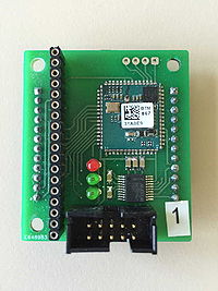
The kart's Bluetooth boards hold a SOC which is programmed as an RS232 modem. The also comprise a legacy RS232 port.
Connectors
The long side single 18-pin row connector is used to program the Bluetooth module.
The 10-pin header connector corresponds to the RS232 port. A flat cable can be crimped with a female header in one side and a female RS232 connector on the other.
An unmounted 4-pin single row connector provides a differential stereo audio output.
Connection between FPGA and Bluetooth module
Both components connect via:
- a serial port link
- an 8-bit parallel port
The serial port is used for sending the controls and receiving the status information.
The parallel port is driven by the Bluetooth module:
- Parallel port bit 0 is brought high when the Bluetooth module has successfully achieved a connection, e.g. with a mobile phone.
Additionally, the FPGA:
- pulses the BT
reset_nline at power-up - drives the BT
VReg_enline high after the reset
Test pins
The DC motor design leaves 4 free pins. Pins 1 to 2 are foreseen for test outputs. Pins 3 and 8 are foreseen for test outputs with a divider by 2 for pulses.
