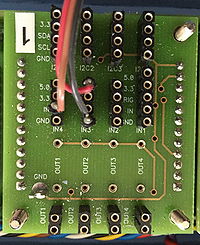
Kart/sensor board
|
End of turn switch
The end of turn switch is located in the I/O board's middle row. It is the 4-pin connector closest to the 5-pin connector. The switch cable is to be connected as:
cable pin green 5 V power supply yellow input
The input has a pull-down resistor. Closing the switch brings a logic '1'.
Hall sensors
The sensor connectors are located in the I/O board's middle row. The sensor cable is to be connected as:
cable pin red 3.3 V or 5 V power supply brown sensor signal black ground
Ultrasound ranger
The sensor connectors are located in the I/O board's middle row. It is the single 5-pin connector. The sensor cable is to be connected as:
cable pin red 5 V power supply yellow measurement start (trig) green echo signal (distance) black ground
Proximity sensors
The sensor connectors are located in the I/O board's side row.
The sensor cable is to be connected as:
cable pin orange 3.3 V power supply yellow SDA green SCL blue ground
LED outputs
The board has 4 LED outputs which can also be used for other purposes, such as buzzers.
The outputs have a common power supply, 2 resistor mount holes and a 2-pin LED connector located on the I/O board's bottom row.
The power supply is connected directly to the 12 V battery packs. The resistor is connected between the power supply and the LED. The LED is connected between the resistor and the ground.
