Kart 2020
(Update Youtube link, remove unused items and section for the 2020 edition) |
|||
| Line 9: | Line 9: | ||
File:Kart I2C.jpg|HES-SO Valais/Wallis Demo Kart | File:Kart I2C.jpg|HES-SO Valais/Wallis Demo Kart | ||
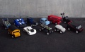
File:SummerSchool_17.jpg|Summer School '17 | File:SummerSchool_17.jpg|Summer School '17 | ||
| − | File:SummerSchool_15.jpg|Summer School '15<br>[https:// | + | File:SummerSchool_15.jpg|Summer School '15<br>[https://youtu.be/hSTDnhofl60 Youtube teaser movie] |
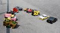
File:SummerSchool_13.jpg|Summer School '13 | File:SummerSchool_13.jpg|Summer School '13 | ||
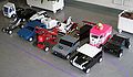
File:SummerSchool_12.jpg|Summer School '12 | File:SummerSchool_12.jpg|Summer School '12 | ||
| Line 19: | Line 19: | ||
The work of the students can be summarized in three main tasks: | The work of the students can be summarized in three main tasks: | ||
* design and assembly of the chassis | * design and assembly of the chassis | ||
| − | |||
* completion and extension of the control GUI on the smartphone | * completion and extension of the control GUI on the smartphone | ||
| Line 30: | Line 29: | ||
A Bluetooth receiver on the kart communicates via an [[kart/serial link|RS232 serial link]] with the FPGA control board. | A Bluetooth receiver on the kart communicates via an [[kart/serial link|RS232 serial link]] with the FPGA control board. | ||
This board stores the control values in a set of [[kart/serial link#Registers|registers]] and dispatches them at a regular interval on an I2C link. | This board stores the control values in a set of [[kart/serial link#Registers|registers]] and dispatches them at a regular interval on an I2C link. | ||
| − | The master also reads data values from the slave boards, stores them into | + | The master also reads data values from the slave boards, stores them into the second set of registers, and sends the corresponding information at a regular pace over the RS232 with a very simple [[kart/serial link#Serial link protocol|protocol]]. |
The control is distributed over several FPGA boards connected together via [[kart/I2C link|I2C]]. | The control is distributed over several FPGA boards connected together via [[kart/I2C link|I2C]]. | ||
| − | These | + | These baseboards each hold a slave function board: |
* A [[Kart/Bluetooth|Bluetooth RS232 modem]] sits on the [[Kart/FPGA board|I2C master FPGA]] | * A [[Kart/Bluetooth|Bluetooth RS232 modem]] sits on the [[Kart/FPGA board|I2C master FPGA]] | ||
| − | * A [[Kart/DC motor controller|DC motor controller]] receives a speed value and builds a PWM and | + | * A [[Kart/DC motor controller|DC motor controller]] receives a speed value and builds a PWM and direction control. |
* A [[Kart/stepper motor controller|stepper motor controller]] receives the desired angle and builds the coil controls signals. | * A [[Kart/stepper motor controller|stepper motor controller]] receives the desired angle and builds the coil controls signals. | ||
| − | * A [[Kart/sensor board|sensor board]] manages I/O comprising proximity sensors, hall sensors (for the driving speed) and LEDs. | + | * A [[Kart/sensor board|sensor board]] manages I/O comprising proximity sensors, hall sensors (for the driving speed), and LEDs. |
== Tasks == | == Tasks == | ||
| − | The [[Media:Programming_Introduction_2020.pdf|programming introduction]] gives an overview | + | The [[Media:Programming_Introduction_2020.pdf|programming introduction]] gives an overview of the structure of the software and the students' tasks. |
They comprise: | They comprise: | ||
* [https://www.android.com Android] application development for the remote control | * [https://www.android.com Android] application development for the remote control | ||
| Line 56: | Line 55: | ||
* You can download the Kart project with the minimal interface here: [[Media:Kart.zip|Kart.zip]] | * You can download the Kart project with the minimal interface here: [[Media:Kart.zip|Kart.zip]] | ||
| − | * You can find the instructions how to open the project in Android Studio in the [[Media:Programming_Introduction_2020.pdf|programming introduction]] presentation... | + | * You can find the instructions on how to open the project in Android Studio in the [[Media:Programming_Introduction_2020.pdf|programming introduction]] presentation... |
* The online documentation of all Java classes that are at your disposition is [[http://kart-javadoc.hevs.ch here]] | * The online documentation of all Java classes that are at your disposition is [[http://kart-javadoc.hevs.ch here]] | ||
* If you need timers, please do not use Java standard Timer and TimerTask, we provide a dedicated Timer class in the package <b>ch.hevs.utils.Timer</b>. | * If you need timers, please do not use Java standard Timer and TimerTask, we provide a dedicated Timer class in the package <b>ch.hevs.utils.Timer</b>. | ||
| Line 84: | Line 83: | ||
The [[Kart/FPGA board|FPGA motherboards]] are equipped with an AGL125 [http://www.microsemi.com/products/fpga-soc/fpga/igloo-overview IGLOO] in a VQ100 package. The clock passed to the FPGA comes from a 10 MHz quartz. | The [[Kart/FPGA board|FPGA motherboards]] are equipped with an AGL125 [http://www.microsemi.com/products/fpga-soc/fpga/igloo-overview IGLOO] in a VQ100 package. The clock passed to the FPGA comes from a 10 MHz quartz. | ||
| − | They hold daughterboards | + | They hold daughterboards that drive different parts of the Kart. |
The motherboards are interconnected via an [[kart/I2C link|I2C link]]. | The motherboards are interconnected via an [[kart/I2C link|I2C link]]. | ||
Revision as of 13:44, 24 August 2020
|
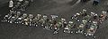
The Kart module (214_Pr1) is a Summer School module for students between the 2nd and the 3rd semester. It is a home-made model car remotely controlled by a smartphone.
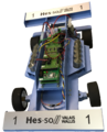
HES-SO Valais/Wallis Demo Kart
Summer School '17
Summer School '15
Youtube teaser movie
Summer School '13
Summer School '12
Summer School '09
Summer School '05
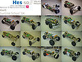
Summer School '04


The work of the students can be summarized in three main tasks:
- design and assembly of the chassis
- completion and extension of the control GUI on the smartphone
System Architecture
The kart is controlled by a smartphone via Bluetooth.
Distributed boards
A Bluetooth receiver on the kart communicates via an RS232 serial link with the FPGA control board. This board stores the control values in a set of registers and dispatches them at a regular interval on an I2C link. The master also reads data values from the slave boards, stores them into the second set of registers, and sends the corresponding information at a regular pace over the RS232 with a very simple protocol.
The control is distributed over several FPGA boards connected together via I2C. These baseboards each hold a slave function board:
- A Bluetooth RS232 modem sits on the I2C master FPGA
- A DC motor controller receives a speed value and builds a PWM and direction control.
- A stepper motor controller receives the desired angle and builds the coil controls signals.
- A sensor board manages I/O comprising proximity sensors, hall sensors (for the driving speed), and LEDs.
Tasks
The programming introduction gives an overview of the structure of the software and the students' tasks. They comprise:
- Android application development for the remote control
The students receive FPGA boards preprogrammed with a functional solution and androïd phones with a demo application.
Android App
One goal is to implement an Android application that controls and monitors the kart.
Introduction
The installable package of the (or rather a) solution can be found here: Kart.apk
Starting point
- You can download the Kart project with the minimal interface here: Kart.zip
- You can find the instructions on how to open the project in Android Studio in the programming introduction presentation...
- The online documentation of all Java classes that are at your disposition is [here]
- If you need timers, please do not use Java standard Timer and TimerTask, we provide a dedicated Timer class in the package ch.hevs.utils.Timer.
- To be informed when a register is modified by the kart (i.e. the hall sensor counter value has changed), your application has to implement the KartStatusRegisterListener interface. This will force your application to have a method (statusRegisterHasChanged) that will be called when a register value has changed. Don't forget to register your listener to the Kart (kart.addStatusRegisterListener(...)).
Common Problems
- Don't block the main thread with an infinite loop
- Don't change the orientation of the display during the execution, it can crash the BT communication. Do it in the Manifest.
Virtual Kart
If you need to test your Android application against a Kart and your Kart is either not build yet or not available at the moment, you can install the Virtual Kart application and use the Kart Bluetooth to USB adapter.
Components
Power supply
The power supply board provides the 5 V and the 3.3 V to the other boards. This is generated from two 6 V battery packs.
The power supply board also comprises an ADC which provides the battery level.
FPGA boards
The FPGA motherboards are equipped with an AGL125 IGLOO in a VQ100 package. The clock passed to the FPGA comes from a 10 MHz quartz.
They hold daughterboards that drive different parts of the Kart. The motherboards are interconnected via an I2C link.
The FPGA motherboards can be tested with the help of a dedicated test board which runs a signal from one I/O pin to the next.
FPGA daughterboards
Existing daughterboards are:
- a Bluetooth interface board
- a DC motor controller
- a stepper motor controller
- an I/O board for the sensors
- an FPGA test board
Sensors
The sensors connected to the I/O board are:
- 1 to 4 VCNL4000 I2C Distance/Ambience Light Sensor
- 1 to 2 SS311PT Hall Sensor
- 1 ultrasound ranger
- 1 end of turn contact switch
Additional Information
- Additional informations for collaborators
- To do list
- When preparing the labs, follow the setup guide