Support/hardware demonstration
From FSI
(Difference between revisions)
(→System) |
(→Set-up) |
||
| (3 intermediate revisions by one user not shown) | |||
| Line 16: | Line 16: | ||
* a power supply cable | * a power supply cable | ||
* a flat band cable | * a flat band cable | ||
| − | * | + | * an [http://wiki.hevs.ch/uit/index.php5/Hardware/Parallelport/heb_rotary HEB board with 4 rotary switches] |
* an oscilloscope | * an oscilloscope | ||
* an oscilloscope cable | * an oscilloscope cable | ||
| + | |||
| + | For the DAC solution, one additionally needs: | ||
| + | * a flat band cable | ||
| + | * a [http://wiki.hevs.ch/uit/index.php5/Hardware/Parallelport/DAC2 HEB DAC board] | ||
| + | * a loudspeaker board | ||
| + | * an RJ45 cable | ||
| + | * a power supply adapter for the loudspeaker board | ||
| + | |||
| + | For the PWM solution, one additionally needs: | ||
| + | * a loudspeaker box with the amplifier on the back side | ||
| + | * a C-shaped FPGA board mezzanine | ||
| + | * an additional oscilloscope cable | ||
= System = | = System = | ||
| Line 32: | Line 44: | ||
The FPGA design can be found in the HEI [https://repos.hevs.ch/svn/eda/VHDL/labs/ELN_support SVN]. | The FPGA design can be found in the HEI [https://repos.hevs.ch/svn/eda/VHDL/labs/ELN_support SVN]. | ||
| − | = | + | = Specifications = |
| − | + | ||
| − | + | ||
| − | + | ||
| − | + | ||
| − | + | ||
| − | + | ||
| − | + | ||
| − | + | ||
| − | + | ||
| − | The | + | The operating frequencies are: |
| − | + | * clock : 66 MHz | |
| + | * sampling : 44.1 kHz | ||
Latest revision as of 14:28, 18 September 2019
|
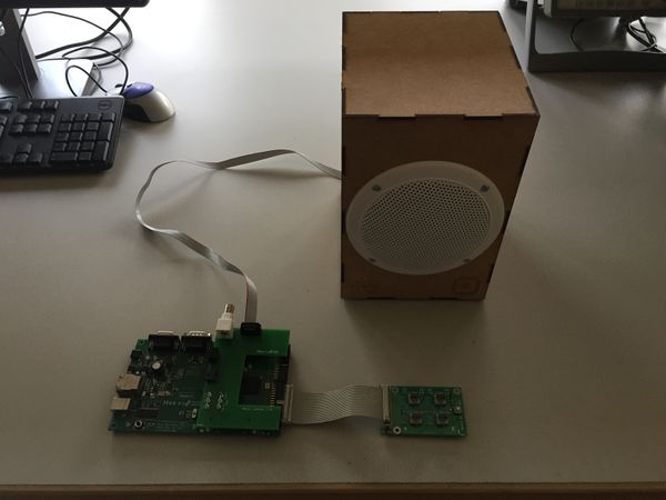
The demonstration system plays tones on loudspeakers.
A button allows to define the number of bits the sinewaves are coded on: This allows to talk of binary numbers.
The foreseen outputs are:
- a loudspeaker with a Digital to Analog Converter (DAC) and an analog amplifier
- a loudspeaker with PWM control and a simple class D amplifier.
Set-up
In order to build the demonstration, one needs:
- an FPGA board
- a power supply cable
- a flat band cable
- an HEB board with 4 rotary switches
- an oscilloscope
- an oscilloscope cable
For the DAC solution, one additionally needs:
- a flat band cable
- a HEB DAC board
- a loudspeaker board
- an RJ45 cable
- a power supply adapter for the loudspeaker board
For the PWM solution, one additionally needs:
- a loudspeaker box with the amplifier on the back side
- a C-shaped FPGA board mezzanine
- an additional oscilloscope cable
System
The following system is used to show digital electronic parts to students.
The block diagram is:
The FPGA design can be found in the HEI SVN.
Specifications
The operating frequencies are:
- clock : 66 MHz
- sampling : 44.1 kHz

