Hardware/FPGAEBS
(Difference between revisions)
m (→Other changes between FPGA-EBS V2.0 and V2.1) |
m |
||
| Line 6: | Line 6: | ||
{|class=wikitable | {|class=wikitable | ||
| − | |- | + | |- bgcolor=#c7c7c7 |
| Type || FPGA-EBS Full board || FPGA-EBS Student board || FPGA-EBS Mezzanine || Schematic || UCF || Description | | Type || FPGA-EBS Full board || FPGA-EBS Student board || FPGA-EBS Mezzanine || Schematic || UCF || Description | ||
|- | |- | ||
| Line 28: | Line 28: | ||
{|class=wikitable | {|class=wikitable | ||
| − | |- | + | |- bgcolor=#c7c7c7 |
| Pin Function || Pin on XC3S500E || Pin on XC3S1200E | | Pin Function || Pin on XC3S500E || Pin on XC3S1200E | ||
|- | |- | ||
Revision as of 10:21, 12 June 2012
|
There are several Version of FPGA EBS Boards
| Type | FPGA-EBS Full board | FPGA-EBS Student board | FPGA-EBS Mezzanine | Schematic | UCF | Description |
| V2.1 | 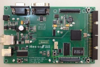 |
 |
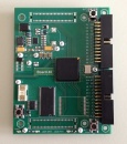 |
FPGA-EBS v2.1 Schematic PDF | FPGA-EBS v2.1 UCF Files | Improved second version of FPGA-EBS comes with Xilinx XC3S500e or XC3S1200E. Note that there is a different UCF Pin constraining file |
| V2.0 | 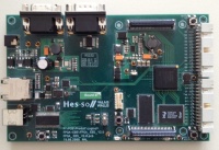 |
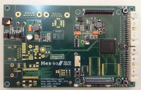 |
Not existing | FPGA-EBS v2.0 Schematic PDF | FPGA-EBS v2.0 UCF Files | Second FPGA-EBS Version comes only with Xilinx XC3S500E |
| V1.0 | 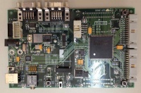 |
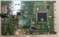 |
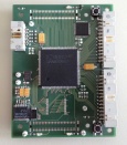 |
FPGA-EBS v1.0 Schematic PDF | Not available | First FPGA-EBS Version comes with a Xilinx XC2S150 or XC2S250 FPGA. Please note that for Spartan 2 is no longer supported by Xilinx, an ISE Version <= 9.2i has to be used |
A VHDL test code with the default UCF Files can be found at:
i:\Institut\Infrastructure\Labos\A309\FPGA\VHDL\ELN_board\
UCF Pin Differences
On the FPGA-EBS v2.X Boards, you can find two different FPGA Spartan3 Chips.
There are 3 Pin differences between Boards with XC3S500E and XC3S1200E.
| Pin Function | Pin on XC3S500E | Pin on XC3S1200E |
| ParallelPort2(16) | F4 | E6 |
| MezzanineData(9) | E17 | E3 |
| sdCke | P15 | P15 |
Other changes between FPGA-EBS V2.0 and V2.1
There are some other changes made in the Ethernet part of those boards. Several bugs were changes and corrected.
- TCT and RCT Pins of the Ethernetconnector were strapped to 3.3V, and decoupled with Capacitors (C59 & C104)
- Serial Capacitors on the RX+ and RX- lines were replaced by 0Ohm Resistors (R61 & R63)
- Proper Reset circuit for the Ethernetphy is put on place (D13, D14, R62 & C108)