Hardware/FPGAEBS
|
A short description of the FPGA-EBS board is found on the ISI Project Page: en, fr.
Board families
There are several versions of FPGA EBS Boards. The stock can be verified and updated on-line.
| Type | FPGA-EBS Full board | FPGA-EBS Student board | FPGA-EBS Mezzanine | Schematic | UCF | Description |
|---|---|---|---|---|---|---|
| V2.2 | None | 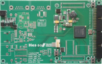 boards 40-70 boards 40-70 |
None | XC3S500e | Adds some bugfixes to the FPGA-EBS and has only been produced as student version with a Xilinx XC3S500E FPGA and a xcf04s Xilinx Platform Flash for persistent configuration. | |
| V2.1 | 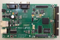 boards 30-35 boards 30-35 |
 boards 11-17 boards 11-17 |
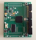 boards 40-41 boards 40-41 |
XC3S1200e XC3S500e |
Improved second version of FPGA-EBS comes with a Xilinx XC3S500E or a XC3S1200E. Note that there is a different UCF Pin constraining file depending on the FPGA type. Furthermore there is a xcf04s Xilinx Platform Flash for persistent configuration. | |
| V2.0 | 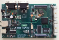 boards 21-28 boards 21-28 |
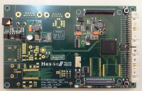 boards 1-8 boards 1-8 |
None | XC3S500e | Second FPGA-EBS Version comes with a Xilinx XC3S500E | |
| V1.0 | 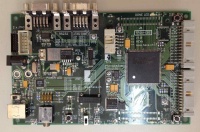 boards 1-3 boards 1-3 |
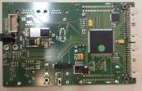 boards 1-8 boards 1-8 |
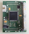 boards 1-15 boards 1-15 |
Not available | First FPGA-EBS Version comes with a Xilinx XC2S150 or XC2S250 FPGA. Please note that Spartan 2 is no longer supported by Xilinx, ISE Version <= 9.2i has to be used |
A VHDL test code with the default UCF Files can be found at the EDA SVN Reopsitory
Power Budget
The TPS750003 Power Management IC provides up to 3A. The whole EBS board consumes 0.17A without any design loaded into the FPGA.
UCF Pin Differences
On the FPGA-EBS v2.X Boards, you can find two different FPGA Spartan3 Chips.
There are 3 Pin differences between Boards with XC3S500E and XC3S1200E.
| Pin Function | Pin on XC3S500E | Pin on XC3S1200E |
|---|---|---|
| ParallelPort2(16) | F4 | E6 |
| MezzanineData(9) | E17 | E3 |
| sdCke | P15 | E4 |
Changes between FPGA-EBS V2.0 and V2.1
There are some other changes made in the Ethernet part of those boards. Several bugs were changes and corrected.
- TCT and RCT Pins of the Ethernetconnector were strapped to 3.3V, and decoupled with Capacitors (C59 & C104)
- Serial Capacitors on the RX+ and RX- lines were replaced by 0Ohm Resistors (R61 & R63)
- Proper Reset circuit for the Ethernetphy is put on place (D13, D14, R62 & C108)
Configuration
This board can be configured in 2 ways:
- directly
- via the onboard Flash memory
For more details see FPGA-EBS Configuration
Stock
The stock comprises:
- V 2.2 : 11 minimal
- V 2.1 : 6 full, 7 student
- V 2.0 : 6 full, 7 student