Hardware/Parallelport/heb microphone
(→Setup) |
|||
| Line 26: | Line 26: | ||
The microphone's output is quite small. | The microphone's output is quite small. | ||
It is first fed to a fixed amplifier through a passive RC highpass. | It is first fed to a fixed amplifier through a passive RC highpass. | ||
| + | After this, it is brought to an amplifier with a variable gain, | ||
| + | and finally to a trigger. | ||
| − | The buzzer/microphone couple have 2 resonant frequencies: one | + | The buzzer/microphone couple have 2 resonant frequencies: one around 3 kHz and the other around 4 kHz. |
The trigger is a [https://en.wikipedia.org/wiki/Schmitt_trigger Schmitt trigger]. | The trigger is a [https://en.wikipedia.org/wiki/Schmitt_trigger Schmitt trigger]. | ||
When there is no signal, the trigger output can be as well low or high. | When there is no signal, the trigger output can be as well low or high. | ||
| + | |||
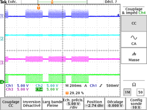
| + | The following picture shows the signal levels | ||
| + | * at the buzzer | ||
| + | * at the output of the first amplifier (testpoint near buzzer) | ||
| + | * at the output of the variable amplifier (Ampli testpoint) | ||
| + | * at the output of the trigger (Trig testpoint) | ||
| + | [[File:Morse levels.png|center|300px|microphone signal levels]] | ||
| + | |||
| + | To come to these signals: | ||
| + | * set the gain of the amplifier with the potentiometer close to the buzzer: screwing reduces the gain | ||
| + | * set the trigger range with the other potentiometer: first unscrew until the output is too noisy then screw until it looks fine. | ||
[[Category:Hardware]] [[Category:Parallelport]] [[Category:HEB]] | [[Category:Hardware]] [[Category:Parallelport]] [[Category:HEB]] | ||
Latest revision as of 15:32, 22 May 2018
|
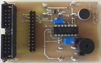
The board was designed for the SEm VHDL FSM lab.
It has a beeper which can emit a Morse code signal and a microphone for receiving it.
| Version | Photo | Schematics | Stock |
|---|---|---|---|
| V1.1 |  |
HEB-microphone Schematic PDF | 10 fully mounted |
Beeper
The beeper is driven directly by a digital I/O line.
Microphone
The microphone's output is amplified and connected to an ADC. The amplified signal is also triggered in order to deliver a simple digital input to the FPGA.
Setup
The microphone's output is quite small. It is first fed to a fixed amplifier through a passive RC highpass. After this, it is brought to an amplifier with a variable gain, and finally to a trigger.
The buzzer/microphone couple have 2 resonant frequencies: one around 3 kHz and the other around 4 kHz.
The trigger is a Schmitt trigger. When there is no signal, the trigger output can be as well low or high.
The following picture shows the signal levels
- at the buzzer
- at the output of the first amplifier (testpoint near buzzer)
- at the output of the variable amplifier (Ampli testpoint)
- at the output of the trigger (Trig testpoint)
To come to these signals:
- set the gain of the amplifier with the potentiometer close to the buzzer: screwing reduces the gain
- set the trigger range with the other potentiometer: first unscrew until the output is too noisy then screw until it looks fine.
