HiRel/CanSat/Slave Power
From FSI
Revision as of 11:48, 3 March 2015 by Oliver.gubler (Talk | contribs)
|
| Type | CanSat Slave Power | Schematic | Description |
|---|---|---|---|
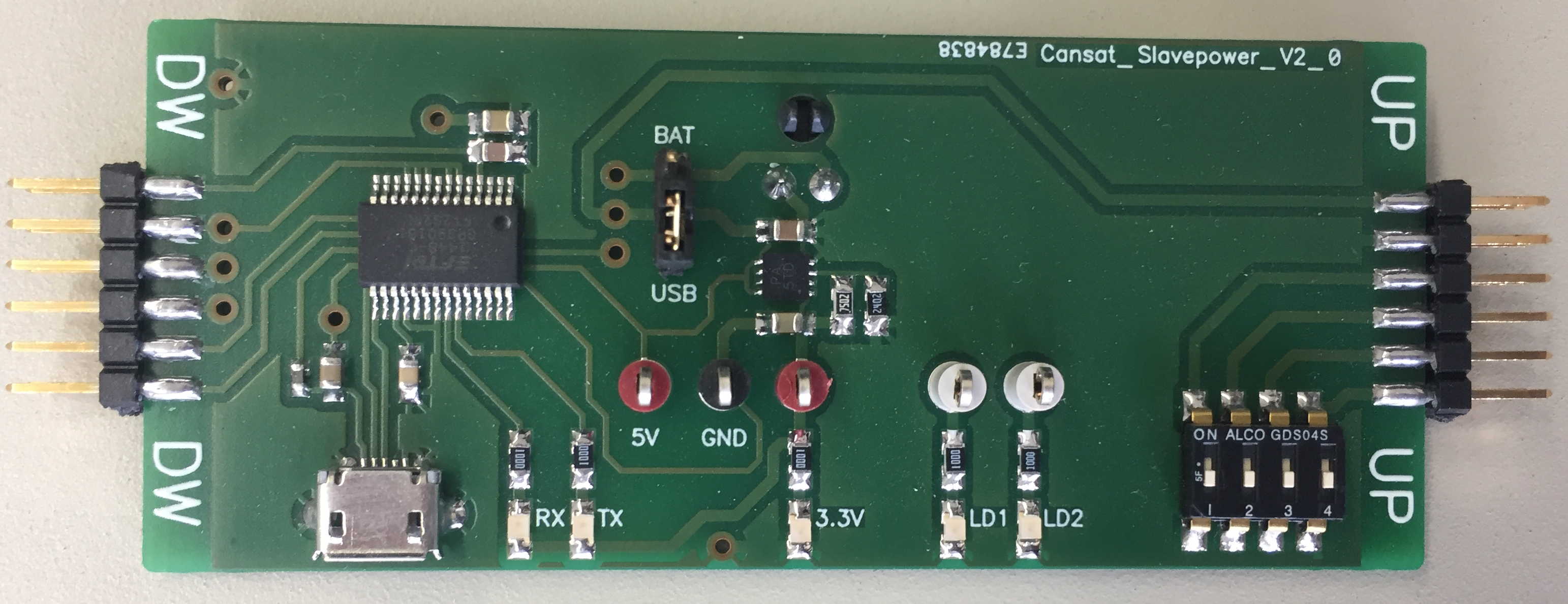
| V1.0 | 200px|CanSat Slave Power V1.0 | CanSat Slave Power v2.0 Schematic PDF |
Power inputs
The CanSat system has 3 possible power sources:
- a mini-USB connector on the power supply board
- a battery connector on the power supply board
- a micro-USB connector on the microprocessor board
Only one of these should power the system with 5 V. Jumpers are provided in order to select the actual power source. This 5 V is distributed to all the boards on the top connector disk.

The power board generates 3.3 V from 5 V. The 3.3 V is distributed to all the boards on the bottom connector disk.
Power usage
The 5 V is used by:
- the power supply board for generating the 3.3 V
- the sensors board for the Max11300 together with the temperature and pressure sensors
The precision of the 5 V is given by the components' requirements:
- the DC/DC converter needs 2.9 V ÷ 5.5 V
- the Max11300 mixed-mode I/O interface needs 4.75 V ÷ 5.25 V
- the pressure sensor needs 4.75 V ÷ 5.25 V
- the temperature sensor needs 2.5 V ÷ 5.5 V
The 3.3 V is used by:
- the FPGA
- the XBee module
- the humidity sensor on the sensors board