Components/IP/SD
|
Sigma-Delta modulator
This IP can be found on the EDA Repository: svn: https://repos.hevs.ch/svn/eda/
The modulator architecture is of Cascaded Integrators with Distributed Feedback (CIDF).
Design
The coefficients can be chosen for the Signal Transfer Function (STF) to match any desired all-pole transfer function. This is done by writing the algebraic form of the modulator's STF and by comparing the denominator coefficients with the one of the desired transfer function. A Maxima script delivers the required coefficients.
An additional parameter, shiftBitNb is used to ensure stability.
Adding 1 to shiftBitNb reduces the STF by one octave (a factor of 2).
This value has to be adjusted within a simulation loop.
VHDL Entity
The VHDL entity of the modulator shows the generics, the inputs and the outputs:
ENTITY sigmaDeltaModulator IS
   GENERIC(
      signalBitNb : positive := 16;
      shiftBitNb  : natural  := 1
   );
   PORT(
      reset      : IN     std_ulogic;
      clock      : IN     std_ulogic;
      en         : IN     std_ulogic;
      parallelIn : IN     signed (signalBitNb-1 DOWNTO 0);
      serialOut  : OUT    std_ulogic
   );
The en would allow to work at a smaller frequency than the clock's.
As Sigma-Delta modulators should work at high rates, en is usually set to 1.
Testbench
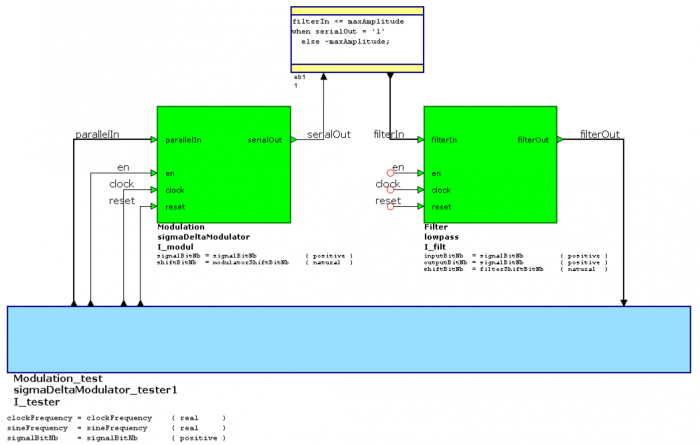
The testbench generates a sinewave input to the modulator.
Clock and signal frequencies are defined as constants in the top-level architecture and passed to the tester via generics.

The modulator output is fed to a lowpass filter which reconstructs the original signal.
The lowpass we use also has a parameter shiftBitNb which can be used to shift the cutoff frequency octave by octave.
As a matter of fact, the testbench filter has the same structure as the sigma-delta modulator.
The only difference is that it hasn't a comparator at the output which reduces it to a single bit.
Lowpass filter setup
The lowpass filter VHDL code allows to select filter order (presently Bessel 2, 3 or 16) by commenting/uncommenting constants at the top of the architecture. For the choice of the filter order, one has to consider the following points:
- Choosing a higher order provides a better Signal-to_Noise Ratio (SNR), but a larger delay
- Selecting a lower order shows ripples in the reconstructed signal, but augmenting
filterShiftBitNbreduces these ripples. On the other hand, choosingfilterShiftBitNbtoo large also leads to a longer delay.
