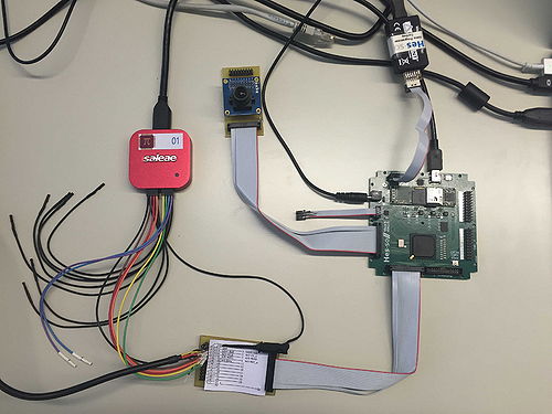
Hardware/CubeSat Gumstix/Test/OV7670 config
From UIT
|
The OV7670 camera can be configures for different image sizes and frame rates.
Configuration
An RS232 interface allows to send configuration commands to the camera.
Power-up settings
At power-up, the test system sets the camera in 352 × 288 CIF mode with RGB output.
The following table provides the register write sequence:
| address | data | comment |
|---|---|---|
| 12 | 80 | COM7: reset |
| 12 | 24 | COM7: CIF resoultion, RGB |
| 11 | 40 | CLKRC: no clock prescaling |
Connection
The camera is connected to the camera interface connector:
| connector pin |
signal | FPGA pin |
function |
|---|---|---|---|
| 1 | 3.3 V | power supply | |
| 2 | GND | ||
| 3 | SClk | A4 | I2C control |
| 4 | SDa | B10 | |
| 5 | VSync | A5 | frame control |
| 6 | HRef | C5 | |
| 8 | Pixel clock | A10 | |
| 22 | XClk | C14 | camera control |
| 23 | CC3 / Reset | B14 | |
| 24 | CC4 / PowerDn | D14 |
The serial port is found on the peripheral 2 connector:
| connector pin |
signal | FPGA pin |
function |
|---|---|---|---|
| 1 | 3.3 V | power supply | |
| 2 | GND | ||
| 3 | TxD | L1 | Serial port |
| 4 | RxD | L3 |
Some camera signals are mirrored on pins 11 to 20 on the peripheral 2 connector.
User interface
In a terminal program:
- typing a "r" launches the initialisation sequence again; the console prints an "r" in return to acknowledge the command
- typing 4 hex digits allow to enter a register address and value; the console prints an "v" in return to acknowledge the command
