Hardware/CubeSat RPi
|
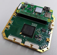
This board is to serve an easy to use demonstrator for a CubeSat On-Board Computer (OBC). It hosts a Raspberry Pi Zero and an FPGA. Two boards are available, one with a Microsemi ProASIC3 and the other with a Microsemi IGLOO FPGA.
| Type | FPGA Rack | Description | |
|---|---|---|---|
| 2019 | 
|
FPGA + RPi 2020 schematic |
FPGAs: ProASIC3 A3P3000, A3P1500, A3P1000 or A3P600 |
Main components
Raspberry Pi
The Raspberry Pi Zero is used as the main processor, typically running Linux.
FPGA
The FPGA does all the real-time work. It is a Microsemi ProASIC3. This device family has been tested for radiation tolerance.
The PCB was foreseen for a M1A3PE3000-2FG484I FPGA. Nevertheless, it should accommodate for AP1500, AP1000 and AP600. Possible variants are:
- AP3000 : basic circuit
- M1AP3000 : circuit with integrated Cortex processor
- AP3000E : extended : has more I/O banks
- AP3000L : low power
Oscillator
The clock oscillator is a 32MHz XO (Standard) CMOS ECS-2033-320-AU.
Connectors
Board to board
The inter-board connection is a serial bus with coaxial cables for Tx and Rx lines. These channels are duplified for reasons of security. To this comes a 0 V, a 3.3 V and 5 V power supply.
All the connections are done by coaxial connectors aligned on both sides of the board. This allows to stack the boards with a coaxial spacer tube. There are 6 connectors per side: 2 for the power, 2 for Tx and 2 for Rx. The power lines are common to both sides of the PCB. The Tx and Rx lines on each side of the PCB are independently connected to the FPGA, thus allowing a token ring communication scheme.
Raspberry Pi to FPGA
All Raspberry Pi (RPi) I/O lines are connected to the FPGA. 5 of them are connected to the FPGA programming lines.
RPi specific I/O are:
| pins | function |
|---|---|
| 3, 5 | I2C 1 |
| 4 | GP CLK 0 |
| 8, 10 | UART 0 |
| 12, 35, 38, 40 | PCM/I2S |
| 19, 21, 23, 24, 26 | SPI 0 |
| 27, 28 | I2C EEPROM |
| 32 | PWM 0 |
| 33 | PWM 1 |
Pins used for the FPGA configuration (via JTAG) are:
| Igloo board pin |
function |
|---|---|
| 13 | reset_n |
| 16 | TMS |
| 18 | TCK |
| 7 | TDO |
| 15 | TDI |
Flat cables
The board has two lateral 20-pin flat cable connectors. Obviously, they are meant for debug purposes.
Power is found on the last pins:
| pin | voltage |
|---|---|
| 17 | 3.3 V |
| 18 | Gnd |
| 19 | 5 V |
| 20 | Gnd |
Programming
The Raspberry Pi Zero loads its operating system from the SD card.
The FPGA can be programmed either from the JTAG connector or from the Raspberry Pi. One has to make sure that the lines on the Raspberry Pi connector are tri-stated when trying to program the FPGA.
Power supplies
The board is powered from a standard 5 V ± 5% (4.75 V to 5.25 V) as defined for USB.
This power supply is used by:
- the Raspberry Pi which generates a 3.3 V for itself
- a DC/DC converter which generates a 1.5 V for the FPGA core from the 5 V power supply
The RPi 3.3 V can be used for the FPGA I/O banks through a 0 Ω resistor if there is no 3.3 V power from the inter-board connector.
The FPGA is supplied with:
| Name | function | voltage |
|---|---|---|
| GND | ground | 0 V |
| GNDQ | quiet ground | 0 V |
| VCOMPLA/B/C/D/E/F | PLL ground | 0 V |
| VCC | core supply | 1.5 V |
| VCCIBx | I/O supply | 3.3 V |
| VMVx | quiet I/O supply | 3.3 V |
| VCCPLA/B/C/D/E/F | PLL supply | 1.5 V |
| VJTAG | JTAG supply | 3.3 V |
| VPUMP | programming supply | 3.3 V |
To do
Any board that doesn't need a modification is obsolete.