Hardware/MiniBioDet
From UIT
(Difference between revisions)
(→Known issues) |
|||
| (3 intermediate revisions by one user not shown) | |||
| Line 12: | Line 12: | ||
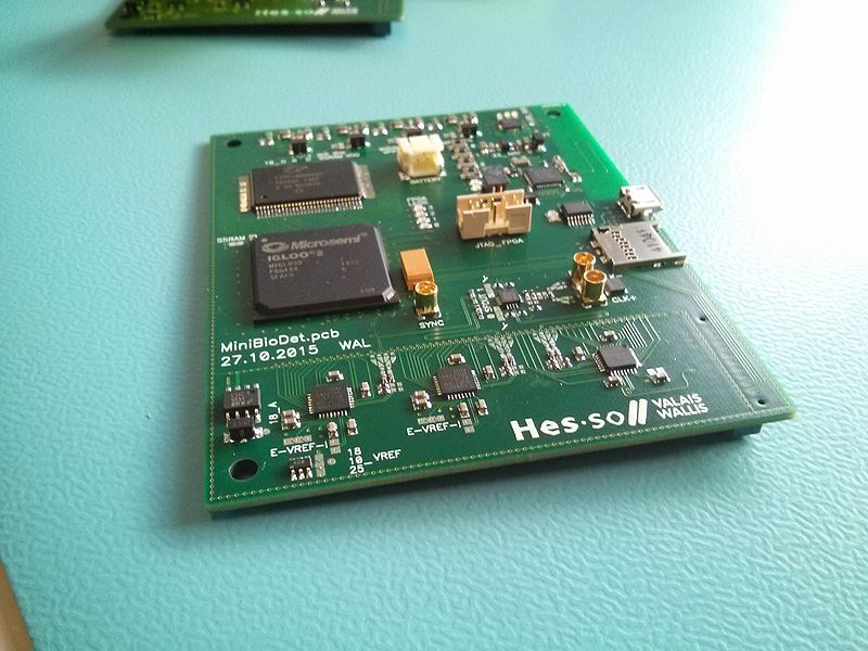
The MiniBioDet is composed of two board : the mother-board and a mezzanine. | The MiniBioDet is composed of two board : the mother-board and a mezzanine. | ||
| − | the mezzanine contains the analog front-end as well as the application specific connectors | + | the mezzanine contains the analog front-end as well as the application specific connectors. |
| − | [[File:MiniBioDet_pcb_monted2.jpg | 800px]] | + | [[File:MiniBioDet_pcb_monted2.jpg | 800px||Fully assembled MiniBioDet V1.00]] |
== Core features == | == Core features == | ||
| Line 76: | Line 76: | ||
== Known issues == | == Known issues == | ||
| + | |||
| + | *tracks of the antenna too thin. | ||
| + | *5V on the NRF through the battery charger led. => not possible to read the charger status. | ||
... | ... | ||
Latest revision as of 23:30, 18 March 2016
|
The main purpose behind this board is to have a FPGA development board specialized in data acquisition and processing, like the FPGA Rack AD/DA V1 and the HES-SO FPGA Rack Hi-Speed AD/DA (HiSADDA) but for low power application and with a small size.
| Type | MiniBioDet | Documentation | Description |
|---|---|---|---|
| V1.0 |   |
Full documentation |
MiniBioDet mother board |
The MiniBioDet is composed of two board : the mother-board and a mezzanine. the mezzanine contains the analog front-end as well as the application specific connectors.

Core features
- Acquisition
- 2x A/D 16bits 20/40/65/80 MSPS (Analog Devices AD9266)
- 1x D/A 14bits 175 MSPS (Analog Devices AD9707)
- FPGA
- 1x IGLOO2 FPGA (Microsemi M2GL050)
- low power
- 56'340 LUTs
- 72 DSP (18x18)
- 6 PLLs/CCCs
- 1826 Kbites RAM
- 1x Low jitter Clock distributor
- 1x SSRAM 36Mbit (Cypress CY7C1460AV25-167AXC)
- 4x user LEDs
- 1x IGLOO2 FPGA (Microsemi M2GL050)
- Interface
- 1x Bluetooth LE uC Soc (Nordic NRF51822)
- 1x FTDI (ft230xs)
- 1x micro SDCard
- 1x FLASH SPI 512 Mbit (Spansion S25FL512S)
- 2x user LEDs
- 4x user Push-buttons
- Power
- 1x LiPo battery charge manager with power-path
- 4x DC/DC power suply
- 2x LDO power suply
- 3x battery status LEDs
- Connectors
- 1x micro USB ( for power and serial port)
- 1x micro SDCard socket
- 2x MMCX for differential external Clock Input
- 1x MMCX for FPGA acquisition synchronization
- 1x battery LiPo connector
- 1x JTAG for the NRF51 SoC
- 1x JTAG for the IGLOO FPGA
- 1x mezzanine connector
Power supply considerations
This board is powered through the USB 5V or with a 3.7V LiPo battery. When a USB port is connected, the battery management circuit directly supplies the card and start charging the battery. The charge status is indicated with three LEDs.
| LED name | LED color | Description |
|---|---|---|
| low batt | red | battery level is low |
| done | green | battery charging is done |
| power | blue | USB power is present |
Bloc diagram

Known issues
- tracks of the antenna too thin.
- 5V on the NRF through the battery charger led. => not possible to read the charger status.