Tools/Xilinx ISE/UCF Timing Constraints
|
Comment
# This is a commentI/O Pad Assigments
  NET "out_sig_slow"    LOC = "S1" | SLEW = SLOW;
  NET "out_sig_fast"    LOC = "S2" | SLEW = FAST;
  NET "out_sig33"       LOC = "V1" | IOSTANDARD = LVCMOS33
  NET "in_sig18"        LOC = "V2" | IOSTANDARD = LVCMOS18
  NET "reset_n"         LOC = "P1" | PULLUP;
  NET "button_Pullup"   LOC = "P2" | PULLUP;
  NET "button_Pulldown" LOC = "P3" | PULLDOWN;
All IO's the same voltage
NET "*" IOSTANDARD = LVCMOS33;
Timing constraints
Clock constraint (PERIOD)
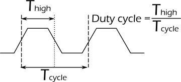
Definition of a clock with a 50% duty cycle and it's frequency (40MHz)
  NET "SYS_CLK" TNM_NET = "SYS_CLK";
  TIMESPEC "tnm_name"   = PERIOD "sig_name" <Tcycle> HIGH <dutycycle>;
  TIMESPEC "TS_SYS_CLK" = PERIOD "SYS_CLK" 25.000 ns HIGH 50.00%;
Time Group
Create timing group with particular net. This code defines a clk_net timing group associated with the CLK clock net and including all synchronous elements controlled by this net (since no qualifier has been specified).
  NET "net_name" TNM_NET = qualifier "tnm_name";
  NET "CLK"      TNM_NET = "clk_net";
  NET "ve_vc<0>" TNM_NET = ve_data;
  NET "ve_vc<1>" TNM_NET = ve_data;
Create timing group by specify the name of the instance (module)
INST "inst_name" TNM = qualifier "tnm_name";
OFFSET
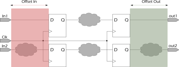
OFFSET constraint is used to specify external setup time for input pads or necessary hold time for output pads.
For input pads, OFFSET specifies a time before the (external) clock edge when the related data signals are set.
  OFFSET = IN 5 ns AFTER  "CLK";
  OFFSET = IN 5 ns BEFORE "CLK";
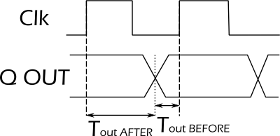
For output pads, OFFSET specifies a minimum time after the clock edge when the related data signals can be deasserted.
  OFFSET = OUT 2 ns AFTER  "CLK";
  OFFSET = OUT 2 ns BEFORE "CLK";
OFFSET with TimeGroup
Set Offset after rising edge of clock constraint for all signals in Timegroup
  TIMEGRP "ve_data" OFFSET = OUT 10.333 ns AFTER "mb_vclk" RISING;
  TIMEGRP "ve_data" OFFSET = OUT 10.333 ns AFTER "mb_vclk" FALLING;
OFFSET with Valid data
The VALID keyword is used in conjunction with the requirement to create a hold time requirement. The VALID keyword specifies the duration of the incoming data valid window. By default, the VALID value is equal to the OFFSET time requirement, which specifies a zero hold time requirement
TIMEGRP DATA_IN OFFSET IN = 2ns VALID 3ns BEFORE CLK RISING;False paths
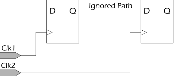
In some cases, you may want to remove a set of paths from timing analysis if you are sure that these paths do not affect timing performance. One common way to specify the set of paths to be removed from timing analysis is to use the FROM-TO constraint with the timing ignore (TIG) keyword. This allows you to:
 * Specify a set of registers in a source time group
 * Secify a set of registers in a destination time group
 * Automatically remove all paths between those time groups from analysis.
To specify the timing ignore (TIG) constraint for this method, define:
 * A set of registers for the source time group
 * A set of registers for the destination time group
 * A FROM-TO constraint with a TIG keyword to remove the paths between the groups
  TIMESPEC "TSid" = FROM "SRC_GRP" TO "DST_GRP" TIG;

  NET "CLK1" TNM_NET = FFS "GRP_1";
  NET "CLK2" TNM_NET = FFS "GRP_2";
  TIMESPEC TS_Example = FROM "GRP_1" TO "GRP_2" TIG;
Multicycle paths
In a multi-cycle path, data is transferred from source to destination synchronous elements at a rate less than the clock frequency defined in the PERIOD specification. This occurs most often when the synchronous elements are gated with a common clock enable signal. By defining a multi-cycle path, the timing constraints for these synchronous elements are relaxed over the default PERIOD constraint. The implementation tools are then able to appropriately prioritize the implementation of these paths. One common way to specify the set of multi-cycle paths is to define a time group using the clock enable signal. This allows you to:
 * Define one time group containing both the source and destination synchronous elements using a common  clock enable signal
 * Automatically apply the multi-cycle constraint to all paths between these synchronous elements
To specify the FROM:TO (multi-cycle) constraint for this method, define:
 * A PERIOD constraint for the common clock domain
 * A set of registers based on a common clock enable signal
 * A FROM:TO (multi-cycle) constraint describing the new timing requirement
  TIMESPEC "TSid" = FROM "MC_GRP" TO "MC_GRP" <value>;

  NET "CLK1" TNM_NET = "CLK1";
  TIMESPEC "TS_CLK1" = PERIOD "CLK1" 5 ns HIGH 50%;
  NET "Enable" TNM_NET = FFS "MC_GRP";
  TIMESPEC TS_Example = FROM "MC_GRP" TO "MC_GRP" TS_CLK1*2;


