Projects/USLO
m |
|||
| Line 7: | Line 7: | ||
The proposed electronic system contains three main parts: | The proposed electronic system contains three main parts: | ||
| − | * a controller | + | * a system controller |
* the mirror controller | * the mirror controller | ||
| − | * the | + | * the data acquisition |
TBD: schematic | TBD: schematic | ||
| Line 17: | Line 17: | ||
= Hardware = | = Hardware = | ||
| − | + | Without using existing hardware as much as possible we would not have been able to build a prototype in such a short time-frame. | |
| − | The Controller is realized on a [[Hardware/FPGARack|HEI FPGA-Rack FPGA board]]. This is a standard FPGA board used at UIT for various projects designed to fit in [http://en.wikipedia.org/wiki/Rack_unit two rack units (2U)]. The controlling is implemented in the [http://www.xilinx.com/products/silicon-devices/fpga/spartan-6/lx.html Xilinx Spartan-6 LX FPGA]. The USB connector is used to send the collected data on to a computer. On the other side, the VME 96 pin connects to other electronic components used for signal transformation. | + | == System Controller == |
| + | |||
| + | The System Controller is realized on a [[Hardware/FPGARack|HEI FPGA-Rack FPGA board]]. This is a standard FPGA board used at UIT for various projects designed to fit in [http://en.wikipedia.org/wiki/Rack_unit two rack units (2U)]. The controlling is implemented in the [http://www.xilinx.com/products/silicon-devices/fpga/spartan-6/lx.html Xilinx Spartan-6 LX FPGA]. The USB connector is used to send the collected data on to a computer. On the other side, the VME 96 pin connects to other electronic components used for signal transformation. | ||
== Mirror Controller == | == Mirror Controller == | ||
| Line 60: | Line 62: | ||
TBD: howland schematic and simulation | TBD: howland schematic and simulation | ||
| − | This functionality was then realized on a | + | This functionality was then realized on a dedicated PCB with a [http://en.wikipedia.org/wiki/Phone_connector_%28audio%29 phone connector] for the input signals from the audio DAC and a [http://en.wikipedia.org/wiki/D-subminiature D-sub] connector towards the mirrors. |
| − | == | + | == Data Acquisition == |
| + | An [http://en.wikipedia.org/wiki/Avalanche_photodiode Avalanche Photodiode (APD)] module captures the light reflected by the eye. We used the [[File:C5460 series kacc1010e06.pdf|Hamamatsu C5460 APD module]]. The output of this module varies between -10 V to 0 V. As the controlling FPGA works best with signals between 0 V and 5 V, a [http://wiki.hevs.ch/uit/index.php5/Hardware/Parallelport/heb_gia general inverting amplifying circuit (HEB_GIA)] has been developed based on the PP board design. The resulting signal is digitized by the PCM1804 full differential analog input 24-BIT, 192-kHz stereo A/D converter on the [[Hardware/Parallelport/Audio_ADC_DAC|HEI PP Audio ADC DAC board]] and send on to the controlling FPGA. | ||
| + | TBD: picture HEB_GIA | ||
| − | == | + | == ISI toaster == |
| + | |||
| + | To provide a compact and transportable system, | ||
[[File:USLO-rack-card.png|300px|thumb|USLO PP Backplane with daughtercards]] | [[File:USLO-rack-card.png|300px|thumb|USLO PP Backplane with daughtercards]] | ||
| Line 72: | Line 78: | ||
The above boards are mounted on PP Backplane board to be inserted into the HEI Rack system to connect to the controlling FPGA. | The above boards are mounted on PP Backplane board to be inserted into the HEI Rack system to connect to the controlling FPGA. | ||
| − | == Synthesis Flow == | + | == Hardware Configuration == |
| + | |||
| + | |||
| + | |||
| + | === Synthesis Flow === | ||
HDL-Designer -> Synplify -> ISE | HDL-Designer -> Synplify -> ISE | ||
Revision as of 10:53, 25 August 2014
|
The aim of the project is to demonstrate the feasibility of a cheap and miniature ophthalmoscope based on versatile and portable MEMS scanning mirrors, capable of three-dimensional measurements of different structures of the fundus, including the optic nerve head, and functional measures requiring excitation. Such a device could be acquired by ophthalmologists, but also by general practice or paramedical staff (orthoptists, nurses and opticians) for the systematic and remote screening of glaucoma. This page describes the electronic system. For details about the optical system see TBD.
System
The proposed electronic system contains three main parts:
- a system controller
- the mirror controller
- the data acquisition
TBD: schematic
The Controller forms the bridge between a computer on one side and the electronic circuitry on the other side. The computer is used to analyze and visualize the collected data. The electronic circuitry transforms the signals from the digital domain into the analogue domain of the mirrors and also from analogue to digital for the image sensor.
Hardware
Without using existing hardware as much as possible we would not have been able to build a prototype in such a short time-frame.
System Controller
The System Controller is realized on a HEI FPGA-Rack FPGA board. This is a standard FPGA board used at UIT for various projects designed to fit in two rack units (2U). The controlling is implemented in the Xilinx Spartan-6 LX FPGA. The USB connector is used to send the collected data on to a computer. On the other side, the VME 96 pin connects to other electronic components used for signal transformation.
Mirror Controller
The mirrors' angle is proportional to a current of ±10 mA and ±15 mA and controlled by an FPGA. For this we use an DAC to transform the digital signal from the FPGA into a tension, and then a Howland Current Pump to transform the tension into current.
TBD: basic schematic
DAC


The DAC in use is the PCM1793 24-BIT, 192kHz Stereo D/A converter on the HEI PP Audio ADC DAC board. This DAC was chosen, because it fulfils the requirements of this project and we had it ready to use on our PP Audio ADC DAC board. This board is designed for audio applications and therefore cancels out any DC-offset. We soldered a 6.4 kΩ pull-up resistor on the positive input of the OpAmp on the Analogue Output Stage. This resistor forms a voltage divider with the 3.3 kΩ resistor to halve the supply voltage.
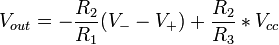
As we like to define the DC current, i.e. when there is no differential voltage applied:
- V − − V + = 0.
Therefore we can simplify:
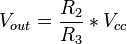
And with this:

As it is a stereo Audio-DAC, it is furnished with 2 channels: left and right. In this application we use one channel per mirror.
Howland Current Pump

A Howloand Current Pump is used to convert the voltage signal from the DAC into a current signal for the mirrors. Thereby we use the "Improved Howland Current Pump" with trimmer (for more information please refer to AN-1515 A Comprehensive Study of the Howland Current Pump).
We did a simulation in P-Spice to better understand the circuit and to specify the resistors' values.
TBD: howland schematic and simulation
This functionality was then realized on a dedicated PCB with a phone connector for the input signals from the audio DAC and a D-sub connector towards the mirrors.
Data Acquisition
An Avalanche Photodiode (APD) module captures the light reflected by the eye. We used the File:C5460 series kacc1010e06.pdf. The output of this module varies between -10 V to 0 V. As the controlling FPGA works best with signals between 0 V and 5 V, a general inverting amplifying circuit (HEB_GIA) has been developed based on the PP board design. The resulting signal is digitized by the PCM1804 full differential analog input 24-BIT, 192-kHz stereo A/D converter on the HEI PP Audio ADC DAC board and send on to the controlling FPGA.
TBD: picture HEB_GIA
ISI toaster
To provide a compact and transportable system,

The above boards are mounted on PP Backplane board to be inserted into the HEI Rack system to connect to the controlling FPGA.
Hardware Configuration
Synthesis Flow
HDL-Designer -> Synplify -> ISE