|
|
| Line 16: |
Line 16: |
| | | | |
| | The board is compatible with the [[Hardware/FPGARackBackplane|FPGA Rack Backplane]] for interconnecting different boards with the help of the [[Standards/HEVs_'VME'_Backplane_Bus|HES-SO Backplane Bus]] and the [[Components/IP/VME|HES-SO VME IP Core]]. Some restrictions due to IOs availablity are shown in the following chapter. | | The board is compatible with the [[Hardware/FPGARackBackplane|FPGA Rack Backplane]] for interconnecting different boards with the help of the [[Standards/HEVs_'VME'_Backplane_Bus|HES-SO Backplane Bus]] and the [[Components/IP/VME|HES-SO VME IP Core]]. Some restrictions due to IOs availablity are shown in the following chapter. |
| − |
| |
| − | = HEVS VME Compatibility =
| |
| − |
| |
| − | {| class="wikitable" style="margin: 0 auto; text-align: center;"
| |
| − | |- style="text-align:left;"
| |
| − | ! style="width:8px"|
| |
| − | ! style="width:64px"|Signal
| |
| − | ! style="width:64px"|Width
| |
| − | ! style="width:64px"|Driver
| |
| − | ! style="width:512px ; text-align:left"|Description
| |
| − | |-
| |
| − | ! style="background:#c6efce" |
| |
| − | | style="background:#3f3f3f" | <span style="color:#FFFFFF">'''Axx'''</span>
| |
| − | | style="background:#ffffff" | 8/16 bit
| |
| − | | style="background:#ffffff" | Master
| |
| − | | style="background:#ffffff ; text-align:left" | Address bus
| |
| − | |-
| |
| − | ! style="background:#7ac1ff" |
| |
| − | | style="background:#3f3f3f" | <span style="color:#FFFFFF">'''Dxx'''</span>
| |
| − | | style="background:#ffffff" | 16/32 bit
| |
| − | | style="background:#ffffff" | Master/Slave
| |
| − | | style="background:#ffffff ; text-align:left" | Data bus
| |
| − | |-
| |
| − | ! style="background:#ffcc77" |
| |
| − | | style="background:#3f3f3f" | <span style="color:#FFFFFF">'''ECCxx'''</span>
| |
| − | | style="background:#ffffff" | 6/8 bit
| |
| − | | style="background:#ffffff" | Master/Slave
| |
| − | | style="background:#ffffff ; text-align:left" | ECC bits (7 Hamming Bits + 1 Parity Bit)
| |
| − | |-
| |
| − | ! style="background:#ff3a3f" |
| |
| − | | style="background:#3f3f3f" | <span style="color:#FFFFFF">'''MCLK'''</span>
| |
| − | | style="background:#ffffff" | 1 bit
| |
| − | | style="background:#ffffff" | Master
| |
| − | | style="background:#ffffff ; text-align:left" | Main bus clock
| |
| − | |-
| |
| − | ! style="background:#ff3a3f" |
| |
| − | | style="background:#3f3f3f" | <span style="color:#FFFFFF">'''RST'''</span>
| |
| − | | style="background:#ffffff" | 1 bit
| |
| − | | style="background:#ffffff" | Master
| |
| − | | style="background:#ffffff ; text-align:left" | ReSeT. Allow the master to reset all slaves racks.
| |
| − | |-
| |
| − | ! style="background:#ffaaff" |
| |
| − | | style="background:#3f3f3f" | <span style="color:#FFFFFF">'''EN'''</span>
| |
| − | | style="background:#ffffff" | 1 bit
| |
| − | | style="background:#ffffff" | Master
| |
| − | | style="background:#ffffff ; text-align:left" | Enables bus transaction.
| |
| − | |-
| |
| − | ! style="background:#ffaaff" |
| |
| − | | style="background:#3f3f3f" | <span style="color:#FFFFFF">'''WR'''</span>
| |
| − | | style="background:#ffffff" | 1 bit
| |
| − | | style="background:#ffffff" | Master
| |
| − | | style="background:#ffffff ; text-align:left" | WRite operation when set, else read operation.
| |
| − | |-
| |
| − | ! style="background:#ffaaff" |
| |
| − | | style="background:#3f3f3f" | <span style="color:#FFFFFF">'''SREADY'''</span>
| |
| − | | style="background:#ffffff" | 1 bit
| |
| − | | style="background:#ffffff" | Slave
| |
| − | | style="background:#ffffff ; text-align:left" | Slave READY. Pulled low by slave when not ready or when ECC error occurs.
| |
| − | |-
| |
| − | ! style="background:#ffaaff" |
| |
| − | | style="background:#3f3f3f" | <span style="color:#FFFFFF">'''MFREEZE'''</span>
| |
| − | | style="background:#ffffff" | 1 bit
| |
| − | | style="background:#ffffff" | Master
| |
| − | | style="background:#ffffff ; text-align:left" | Master FREEZE. Set by the master for freeze the bus when ECC error occurs.
| |
| − | |-
| |
| − | ! style="background:#ffaaff" |
| |
| − | | style="background:#3f3f3f" | <span style="color:#FFFFFF">'''MODE'''</span>
| |
| − | | style="background:#ffffff" | 1 bit
| |
| − | | style="background:#ffffff" | Master
| |
| − | | style="background:#ffffff ; text-align:left" | '1' is 64k*32bit slave card and '0' 256*16bit slave card. Used as MSB bit of address.
| |
| − | |-
| |
| − | ! style="background:#7fff7a" |
| |
| − | | style="background:#3f3f3f" | <span style="color:#FFFFFF">'''WCLKx'''</span>
| |
| − | | style="background:#ffffff" | 2 bit
| |
| − | | style="background:#ffffff" | Undef.
| |
| − | | style="background:#ffffff ; text-align:left" | Additionnal clock lines.
| |
| − | |-
| |
| − | ! style="background:#ffee77" |
| |
| − | | style="background:#3f3f3f" | <span style="color:#FFFFFF">'''IRQxx'''</span>
| |
| − | | style="background:#ffffff" | 8 bit
| |
| − | | style="background:#ffffff" | Undef.
| |
| − | | style="background:#ffffff ; text-align:left" | User-defined interrupt bits.
| |
| − | |-
| |
| − | ! style="background:#DA9694" |
| |
| − | | style="background:#3f3f3f" | <span style="color:#FFFFFF">'''UART_TXD'''</span>
| |
| − | | style="background:#ffffff" | 1 bit
| |
| − | | style="background:#ffffff" | Master
| |
| − | | style="background:#ffffff ; text-align:left" | UART-Bus transmission line
| |
| − | |-
| |
| − | ! style="background:#DA9694" |
| |
| − | | style="background:#3f3f3f" | <span style="color:#FFFFFF">'''UART_RXD'''</span>
| |
| − | | style="background:#ffffff" | 1 bit
| |
| − | | style="background:#ffffff" | Slave
| |
| − | | style="background:#ffffff ; text-align:left" | UART-Bus receiving line
| |
| − | |-
| |
| − | ! style="background:#b1a0c7" |
| |
| − | | style="background:#3f3f3f" | <span style="color:#FFFFFF">'''SPI_CLK'''</span>
| |
| − | | style="background:#ffffff" | 1 bit
| |
| − | | style="background:#ffffff" | Master
| |
| − | | style="background:#ffffff ; text-align:left" | SPI-Bus clock signal
| |
| − | |-
| |
| − | ! style="background:#b1a0c7" |
| |
| − | | style="background:#3f3f3f" | <span style="color:#FFFFFF">'''SPI_MISO'''</span>
| |
| − | | style="background:#ffffff" | 1 bit
| |
| − | | style="background:#ffffff" | Slave
| |
| − | | style="background:#ffffff ; text-align:left" | SPI-Bus Master In Slave Out
| |
| − | |-
| |
| − | ! style="background:#b1a0c7" |
| |
| − | | style="background:#3f3f3f" | <span style="color:#FFFFFF">'''SPI_MOSI'''</span>
| |
| − | | style="background:#ffffff" | 1 bit
| |
| − | | style="background:#ffffff" | Master
| |
| − | | style="background:#ffffff ; text-align:left" | SPI-Bus Master Out Slave In
| |
| − | |-
| |
| − | ! style="background:#b1a0c7" |
| |
| − | | style="background:#3f3f3f" | <span style="color:#FFFFFF">'''SPI_CS0'''</span>
| |
| − | | style="background:#ffffff" | 1 bit
| |
| − | | style="background:#ffffff" | Master
| |
| − | | style="background:#ffffff ; text-align:left" | SPI-Bus Chip-Select 0
| |
| − | |-
| |
| − | ! style="background:#b1a0c7" |
| |
| − | | style="background:#3f3f3f" | <span style="color:#FFFFFF">'''SPI_CS1'''</span>
| |
| − | | style="background:#ffffff" | 1 bit
| |
| − | | style="background:#ffffff" | Master
| |
| − | | style="background:#ffffff ; text-align:left" | SPI-Bus Chip-Select 1
| |
| − | |-
| |
| − | ! style="background:#c4bd97" |
| |
| − | | style="background:#3f3f3f" | <span style="color:#FFFFFF">'''I2C_SCL'''</span>
| |
| − | | style="background:#ffffff" | 1 bit
| |
| − | | style="background:#ffffff" | Master
| |
| − | | style="background:#ffffff ; text-align:left" | I2C-Bus clock line
| |
| − | |-
| |
| − | ! style="background:#c4bd97" |
| |
| − | | style="background:#3f3f3f" | <span style="color:#FFFFFF">'''I2C_SDA'''</span>
| |
| − | | style="background:#ffffff" | 1 bit
| |
| − | | style="background:#ffffff" | Bi-Directionel
| |
| − | | style="background:#ffffff ; text-align:left" | I2C-Bus data line
| |
| − | |-
| |
| − | ! style="background:#3f3f3f" |
| |
| − | | style="background:#3f3f3f" | <span style="color:#FFFFFF">'''+12V'''</span>
| |
| − | | style="background:#ffffff" | -
| |
| − | | style="background:#ffffff" | Backplane
| |
| − | | style="background:#ffffff ; text-align:left" | +12V as defined by the VME Standart
| |
| − | |-
| |
| − | ! style="background:#3f3f3f" |
| |
| − | | style="background:#3f3f3f" | <span style="color:#FFFFFF">'''-12V'''</span>
| |
| − | | style="background:#ffffff" | -
| |
| − | | style="background:#ffffff" | Backplane
| |
| − | | style="background:#ffffff ; text-align:left" | -12V as defined by the VME Standart
| |
| − | |-
| |
| − | ! style="background:#3f3f3f" |
| |
| − | | style="background:#3f3f3f" | <span style="color:#FFFFFF">'''USER_VDD'''</span>
| |
| − | | style="background:#ffffff" | -
| |
| − | | style="background:#ffffff" | Backplane
| |
| − | | style="background:#ffffff ; text-align:left" | Free definable user voltage
| |
| − | |-
| |
| − | ! style="background:#3f3f3f" |
| |
| − | | style="background:#3f3f3f" | <span style="color:#FFFFFF">'''+5V_F'''</span>
| |
| − | | style="background:#ffffff" | -
| |
| − | | style="background:#ffffff" | Backplane
| |
| − | | style="background:#ffffff ; text-align:left" | Filtered +5V for all "Clean" consumers
| |
| − | |-
| |
| − | ! style="background:#3f3f3f" |
| |
| − | | style="background:#3f3f3f" | <span style="color:#FFFFFF">'''+5V_N'''</span>
| |
| − | | style="background:#ffffff" | -
| |
| − | | style="background:#ffffff" | Backplane
| |
| − | | style="background:#ffffff ; text-align:left" | +5V for all "Noisy" consumers
| |
| − | |-
| |
| − | ! style="background:#3f3f3f" |
| |
| − | | style="background:#3f3f3f" | <span style="color:#FFFFFF">'''+3.3V'''</span>
| |
| − | | style="background:#ffffff" | -
| |
| − | | style="background:#ffffff" | Backplane
| |
| − | | style="background:#ffffff ; text-align:left" | Filtered +3.3V voltage for all "clean" consumers
| |
| − | |-
| |
| − | ! style="background:#3f3f3f" |
| |
| − | | style="background:#3f3f3f" | <span style="color:#FFFFFF">'''GND_N'''</span>
| |
| − | | style="background:#ffffff" | -
| |
| − | | style="background:#ffffff" | Backplane
| |
| − | | style="background:#ffffff ; text-align:left" | Gnd for all "Noisy" Voltages. That means -12V / +12V / User_VDD / +5V_N
| |
| − | |-
| |
| − | ! style="background:#cccccc" |
| |
| − | | style="background:#3f3f3f" | <span style="color:#FFFFFF">'''GND_F'''</span>
| |
| − | | style="background:#ffffff" | -
| |
| − | | style="background:#ffffff" | Backplane
| |
| − | | style="background:#ffffff ; text-align:left" | Ground for all "Clean" Voltages e.g. +5V_F / +3.3V
| |
| − | |}
| |
| | | | |
| | = Hardware features = | | = Hardware features = |
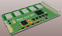
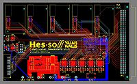
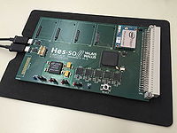
The board comprises a controller FPGA and Linux microprocessor systems.
It is tailored for low-power, real-time image processing.


